

|
LEGACY TOWERS PROJECT
SEATTLE, WA
Temporary VENIS© Shoring Wall
| |
When Legacy Partners and the Fria Company requested bids for a 25,000 square foot Owner-Design conventional shoring wall, as well as a proposal for a Design-Build alternate, Ground Support PLLC and Malcolm Drilling Company Inc. proposed the VENIS© system, with roughly a 25% cost savings compared to the Owner-Designed shoring system.
|

|
|
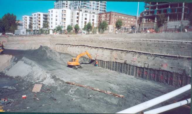
View from the Northwest of the East and South Walls After Completion
|
PROJECT BACKGROUND
- Subsurface conditions consisted of 10- to 15-ft of fill underlain by glacial soils. The glacial soils consisted of an erratic sequence of recessional outwash, transitional materials, and hard silts and clays.
- The groundwater table was encountered near the base of the fill. Dewatering wellpoints were installed to depressurize the face of the excavation.
- Three-sided excavation along Broad Street, Western Avenue, and Clay Street, North of downtown Seattle.
- Excavation was up to 42-ft deep, with over 25,000 square feet of shoring wall face, and was surrounded by a variety of deep electrical and telephone duct banks and vaults.
- Because of the nature of the fills and recessional outwash, and the presence of groundwater, it was generally agreed that standard soil nailing was not practical due to inadequate face stability. Therefore, the Owner-Design consisted of a conventional anchored soldier pile and timber-lagging wall.
|

|
|
View from the Southwest of the East and North Walls After Completion
|
SHORING DESIGN SUMMARY
- Ground Support and Malcolm Drilling proposed a Design-Build alternate to the Owner-Design shoring system. The Owner-Design conventional shoring wall was bid at roughly $40 per square foot (SF) of wall face. The Design-Build alternate VENIS© system was bid at just under $30 per SF, for a $10 per SF savings to the Owner.
- VENIS© stands for Vertical Element and Nail Integrated Support system. The shoring system combines a modified facing system with standard soil nails in order to deal with adverse face stability conditions that would normally require a timber-lagged shoring wall.
- In most situations, the VENIS© system will be more economical than conventional shoring. The most beneficial situations will occur when the VENIS© system is used to get through upper less competent soils, below which standard soil nailing may be used in underlying more competent ground.
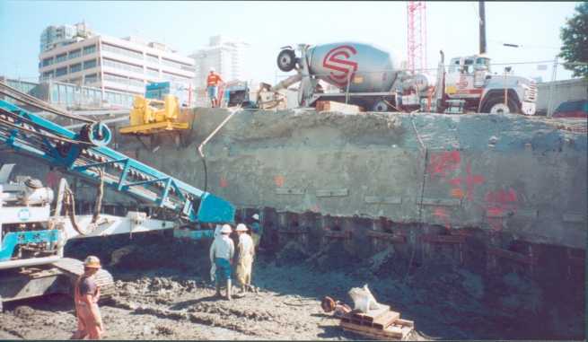
- The presence of deep utility duct banks and vaults required that the first row of soil nails be installed from 5- to 13-ft below existing grade. This was accomplished to some extent through the use of sloped cuts, but mainly through the use of high cantilevers in the vertical elements above the first row of soil nails.
|

|
|
View of Soil Nail Installation
|

|
|
View of Wall Face Excavation
|
SHORING CONSTRUCTION SUMMARY
- The soil nail support system on this project generally consisted of a 6-ft horizontal by 7- to 8-ft vertical staggered soil nail pattern. The increased vertical nail spacing is possible with the presence of the vertical elements, allowing the elimination of 1 or 2 rows of soil nails.
- The facing system was comprised of vertical elements on 3-ft spacings around the site perimeter. The soil nails were attached to the vertical elements with walers and shotcrete lagging was connected to the vertical elements with headed studs.
- Face stability problems were essentially non-existent in all of the soils. Prior to application of shotcrete lagging, vertical cuts of 6- to 8-ft in height stood well for days with essentially no fallout or sloughing.
- Wall face excavation was simplified because the excavator would run the hoe bucket down the face of the piles, prohibiting inadvertent over-excavation.
- · Because of the simplified facing design and the large vertical nail spacing, installation of shotcrete lagging was very efficient and productive. It was not uncommon to exceed 2000 SF of shotcrete facing installation per day.
- Optical survey monitoring was performed along the edge of the adjacent streets and at the top of the vertical elements. The measured lateral and vertical movements were typically less than ¼ inch on average and never exceeded ½ an inch anywhere.
|
|
|

